Do it yourself: Building your own Ambilight
Two guys stick Christmas decoration on a TV and hook it up to a mini PC named after a berry. An Ambilight is born. Just another day at the digitec office.
In theory, Ambilights are only available from Philips. At least that’s what I thought until Category Marketing Specialist and self-proclaimed do-it-yourselfer Quentin Aellen sends me a message.
Hey Luca. You’re the man when it comes to TVs, right? I’ve got a bit of a project idea. I want to turn every TV into an Ambilight TV.
Obviously, I think the idea’s pretty cool:
Hell yeah! Sounds like a plan. Cool idea, Quentin.
Quentin is happy. He was expecting to put a lot of effort into persuading me and had even put together a solid set of arguments to explain why his idea wasn’t as daft as it sounded. After all, making a homemade Ambilight isn’t just a good story but genuine added value for any reader who decides to copy the experiment.
According to Philips, Ambilight adds another dimension to your TV by radiating light from the sides and filling your room with the perfect ambience. The colour of the light projected to your wall is matched to everything that is happening on screen. Depending on the Ambilight model, the lights are:
- on 2 sides, to the left and right of your TV
- on 3 sides with an additional one at the top
- on 4 sides, i.e. on all sides
Let me give you an example: You’re watching Luke Skywalker being attacked by Tusken Raiders in the middle of the Jundland Wastes of Tatooine. The LED lights on your TV simultaneously project orange-yellow lights on your living room wall. Not bad, eh?
Quentin and I bounce a few ideas off each other about how this should work in theory, what material will be needing and how much time it will take us. Quentin adds:
It will be awesome. And easy to do.
That last sentence echoes in my mind. «And easy to do», he said. I’m not too sure about that and must admit that I’m no do-it-yourselfer. But if anybody knows what he’s doing, it’s Quentin. I get my hopes up.
«It will be awesome», ambition whispers in my ear.
If Quentin manages to give me the knowledge I need to equip my TV with Ambilight-enabled Christmas lights, then I’m confident he can do the same for you – no matter how clumsy you may be. If you think you’re a layperson, worry not. Let us tread this path together. My aim is to inspire you to be a home cinema do-it-yourselfer. Sounds fun, right?
Let’s do this!
Here we go, and this is the plan
Source: Stefania Krähenbühl
Before you sign up for this, let me explain in simple terms what we’re trying to build. Our Ambilight system consists of the following three cornerstones:
- The entertainment system: The signal source itself. E.g. your TV, Blu-Ray player or game console.
- The Raspberry Pi: The brain that receives and interprets the signals sent by the source. After all, somebody’s got to tell the LEDs behind the TV when they should change colour. For technological reasons, the brain cannot be the processor that’s inside the TV.
- The LEDs: We want to stick them to the back of the TV and they will shine in different colours.
To put it in a nutshell:
- The entertainment system sends signals to...
- ...the Raspberry Pi, which interprets them and...
- ...tells the LEDs behind the TV what colour they should be projecting.
«It will be awesome. And easy to do», to quote Quentin’s mantra.
Before we start working on our Ambilight system, there’s quite a bit of stuff that needs to be ordered. I’ll be listing said stuff bit by bit to avoid overwhelming you with a list of products. And I’ll tell you what else you’ll need. Like your head or patience or a fat wallet.
Day 1: The first step with LED lights and juice
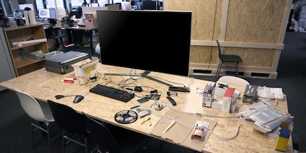
We start with the difficult bit. This is the moment to summon my non-existent internal handyman. Plus we need:
- A television to equip with Ambilight
- The confidence to do a tiny bit of soldering at beginner level
- About 150 francs
- The following products:
We lay out all the parts. Even those we will be needing later on.
«Whoa, that’s quite a lot», I goggle.
«That’s normal», Quentin replies calmly.
We start with the LED tape. The LEDs will be stuck around the TV at a later stage. As the strips can’t go around corners, we need to precut them. Two for the sides and two for the top and bottom. We use sidecutters to snip them into shape.
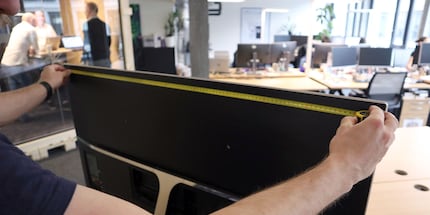
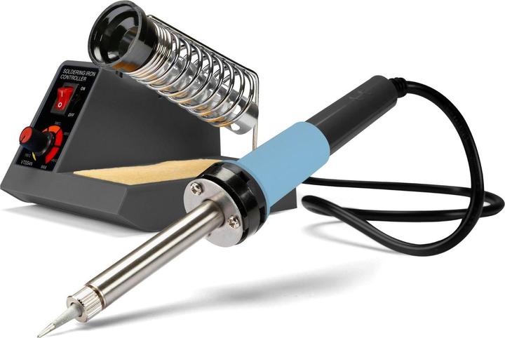
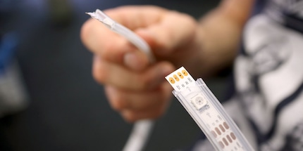
The cut is made between the so-called connectors. They serve a very particular purpose: The upper connector (vcc) stands for volt. This is where the power goes to give the LEDs enough juice to shine brightly. The lower connector is the earthing or grounding to let the power escape. The Raspberry Pi sends it signals through the two middle connectors – clock and data. These signals tell the lights in which colour and how bright they should shine.
«Are you good at soldering?», the self-proclaimed do-it-yourselfer asks.
«No idea. Maybe. I can play the piano?», I reply in an attempt to camouflage my soldering virginity.
«Meaning?», he insists.
«I’m on the “basic-beginner-I’ve-never-touched-anything-like-it-help” level», I reluctantly admit.
Quentin smiles. He tells me not to worry and predicts that I will soon fall in love with the sweet smell of burnt tin. He gives me a big grin. I’m telling you, he’s a true handyman.
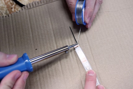
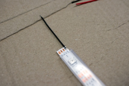
The reason for all the questions is that we need to reconnect the four pieces of LED strip. To do so, you need to hold the hot soldering iron against the soldering tin and let it drip onto the contact points. Quickly stick in the cable before the silver liquid solidifies again. The order of the LED strips is as follows: short, long, short long. I watch the expert before giving it a go myself.
Five minutes later, I’m surprised I haven’t set light to the table.
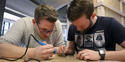
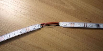
All it takes is a little more soldering and the LED chain is complete. We solder together all four connectors between two strips – volt, data, clock and ground. Quentin and I make sure the drops of tin and soldering cables don’t touch each other. My imagination runs wild and I picture everything blowing up in our faces if they did.
I decide not to push my luck.
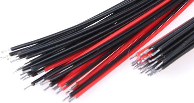
We’ve reached the last strip and only solder one soldering cable at the upper (vcc) and lower connector (ground) without connecting it with a further LED strip. We’ve ignored the two connecting points in between. Why? Because we still need room for the Raspberry Pi. If we were to close the circle, there would be no input point for it.
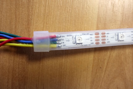
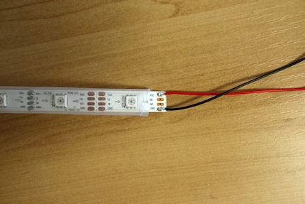
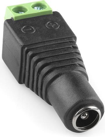
But for now, it’s all about power. For the first and last strip, we take the soldering cables through which the current will flow (vcc), twist the ends together and stick them into the positive pole of the adapter that will later be hooked up to the power supply. Using a screwdriver, the screw is twisted tight to avoid the cables slipping out. We repeat the procedure for the two earthing cables – the only difference being that they go into the negative pole of the adapter.
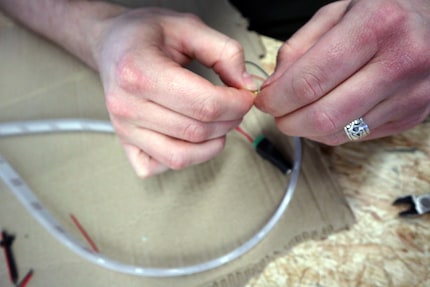
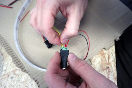
Now for the first test. We connect the adapter with the power supply. If we’ve done everything properly, the LEDs should shine brightly.
Nothing happens. The LEDs stay dark.
«I probably messed up the soldering», I say apologetically.
«I don’t think so», he answers calmly, «it looks impeccable. Maybe the LEDs aren’t getting enough juice».
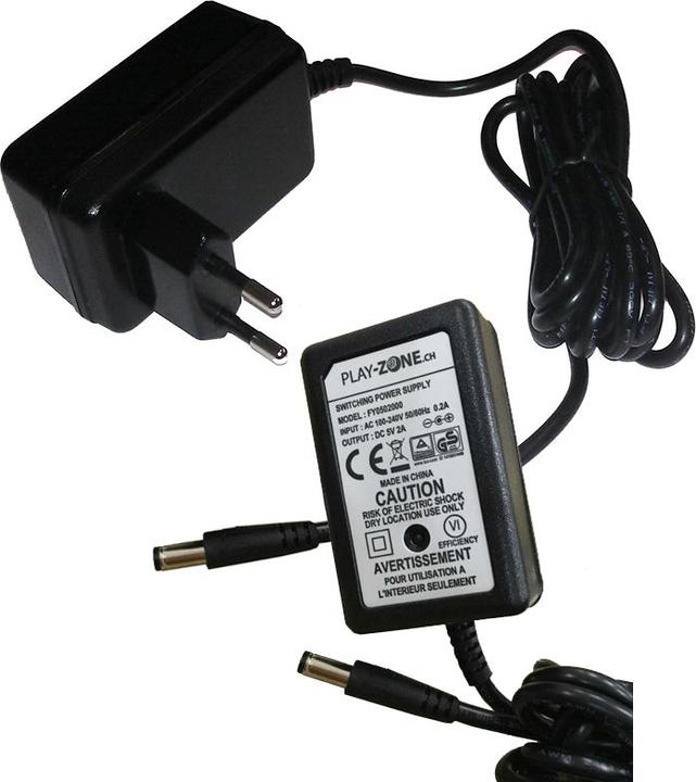
Indeed, the power supply is too weak. As it doesn’t have enough ampere, it’s not providing enough watts of power. We get ourselves a new one.
Day 2: We’ve got the power. Time to configure the Raspberry Pi.
If at first you don’t succeed, try, try again.
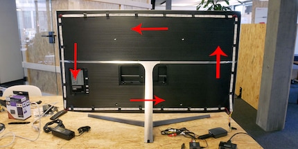
Quentin and I are excited. We replace the power supply and are relieved to see that the LEDs are doing their job. Finally, we can stick them to the TV. We start at the bottom right with the first short strip and keep working counterclockwise. Above, you can see how we’ve done that.
«The hardest part is already behind you», Quentin says encouragingly. Little does he know what obstacles we have yet to overcome.
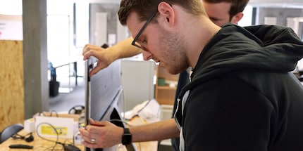
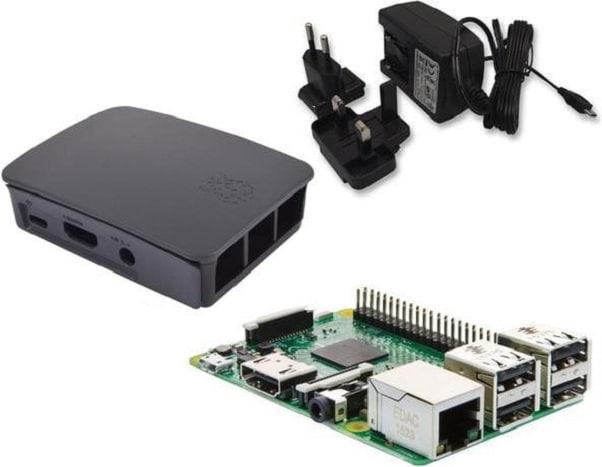
And now for the second elemental pillar and brain of our system: The Raspberry Pi. The RasPi is basically a mini computer that can do everything a big computer can. It’s equipped by default with Linux and now we need to configure the Raspberry Pi so that it can later process the signals from the source.
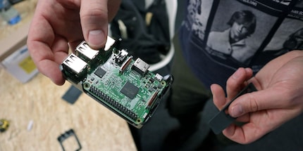
What we need:
- A Raspberry Pi
- A mouse and keyboard to operate the Raspberry Pi
- A second laptop / PC, to configure the software before it’s sent to the RasPi
- About 80 francs
- The following products:
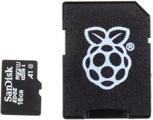
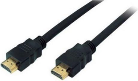
To explain how we set up the brand-new RasPi would go beyond the scope of this article. Fortunately, Senior Editor Dominik Bärlocher already explained how it is done a while back. Don’t worry, it’s not rocket science. To set up the Raspberry Pi, we use an HDMI cable to hook it up to the TV that will later be equipped with Ambilight. The mouse and keyboard are connected to the RasPi through a USB port.
Heads up, here comes the critical bit. There’s a lot of «click here» and «check box there». We have to bite the bullet.
We download the programme Hyperion to our second laptop. It’s kind of a configuration software for our Ambilight. We open the jar file with a right click, «open with» und «Java». It’s just like an Exe file. The only prerequisite is that Java is pre-installed.
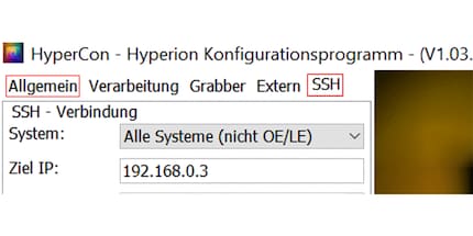
Quentin clicks on the «SSH» tab at the top left, selects «all systems» under system and enters the destination IP address of the RasPi. He found out the IP address by clicking on the «control» window on the Raspberry Pi desktop (the icon that shows a small black monitor at the top left). While he was at it, he activated the SSH on the RasPi. To do so, he clicked on the raspberry at the top right, then on «Raspberry Pi Configuration» and finally on «Interfaces». For the SSH he checked the «Enable» box.
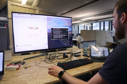
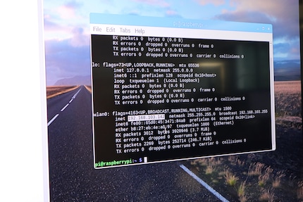
Back to Hyperion. As regards user name and password, we’re not changing anything. Instead, Quentin clicks on the «Connect» button. It takes a few scary seconds for Hyperion to connect with the RasPi. Several buttons and tabs open in the programme. Quentin clicks on «Inst./Akt. Hyperion» to make Hyperion install itself on the Raspberry Pi. A white window opens and for a long time nothing happens.
«Is that normal?», I ask after five minutes have gone by.
As always, Quentin is totally zen: «Totally. The programme did warn us after all».
True. «Be patient» was mentioned at some point.
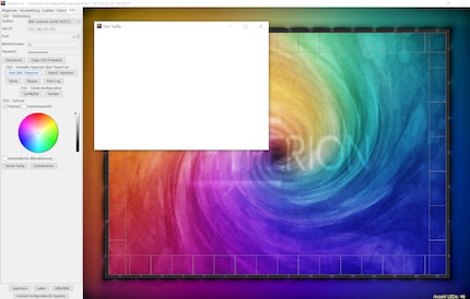
Finally, something’s happening. A line that roughly reads «done» pops up. So in summary, we’ve connected Hyperion with the RasPi and installed the programme on it. Now it’s time for the configuration, which we also do from our laptop.
Quentin goes back to the «general» tab. Under «type», we select the LED type that we are using for our Ambilight. In our case it’s the «APA102». The next step is to specify how many LEDs are attached horizontally and vertically to the back of the TV. For our 49-inch Samsung, there are thirty LEDs that run horizontally and seventeen that run vertically. Hyperion numbers the LEDs automatically. That’s from zero to 93 in our case.
Hyperion wants to know two more things:
- In which direction do the LEDs run when you’re looking at the TV from the back?
- Where does the circuit begin. In other words, where is the first series of LEDs located that is connected to the RasPi?
The first question is easy to answer. Quentin selects «counter clockwise». As regards the second question, he needs to click through the numbers under «LED start» until the preview picture shows the «zero LED» in the bottom left corner or: «LED start» on «-17».
With this, we’ve done a rough configuration. Now, Quentin and I have to directly connect the LEDs with the RasPi. The LED tape comes with soldering cables on the data and clock connectors ex factory. As a quick reminder: They are needed to receive signals from the Raspberry Pi and send them to the LEDs.
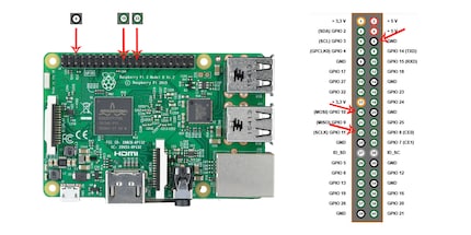
The blue cable (clock) goes in the 12. pin from the right in the bottom row. The green cable (data) goes in the 10. pin from the right in the bottom row. Then there’s the black cable (ground) of the power supply itself that is in charge of earthing. That one goes in the 3. pin from the right in the upper row.
«Another test?», I ask impatiently. I’m dying to see this thing in action!
Quentin opens the Internet browser of the Raspberry Pi and goes to YouTube. He opens a video in full screen mode – the LEDs glitter and gleam. Quentin and I high five each other. The bandwidth of the RasPi isn’t good enough to play the video smoothly; the LEDs match this with a lazy light display.
«It’s not like you’re going to watch TV with your RasPi», Quentin says reassuringly. «All the mini computer will do is be in charge of thinking on behalf of the LEDs. It won’t be generating the video signal».
The picture you see on the TV is generated by the Raspberry Pi.
Makes sense. I think we’ve done enough DIY for today.
Day 3: The moment of truth is nigh
It’s still quite early but Quentin’s wide awake and ready to go. First, he tells me what steps are ahead of us.
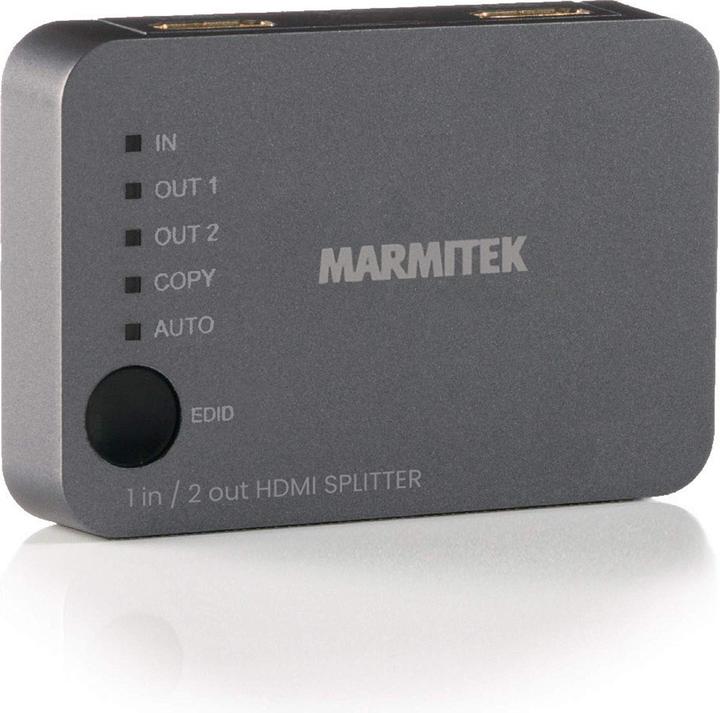
«The video signal comes from an external system such as a video game console or a Blu-ray player». He reaches for a Switcher by Marmitek and says «the video signal needs to be split so we can send it to both the TV and the RasPi. After all, we don’t just want the TV to show videos but the RasPi to interpret the signals and tell the LEDs what to do».
What we need:
- An external source (PC, Blu-ray player, video game console, receiver)
- About 150 francs
- The following products:
You may have noticed that I listed a «splitter» in the above list even though Quentin was waving a «switcher» about. What can I say. We failed the idiot test and tried to split the video signal with a switcher. Obviously, that doesn’t work. Don’t be like us. Buy a splitter right away. It will save you money and energy.
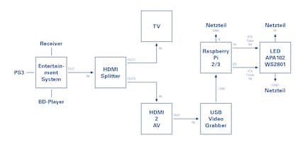
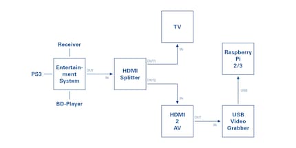
I insert the same diagram as above but zoom in a little. This should make the following line of text easier to understand.
Source: Stefania Krähenbühl
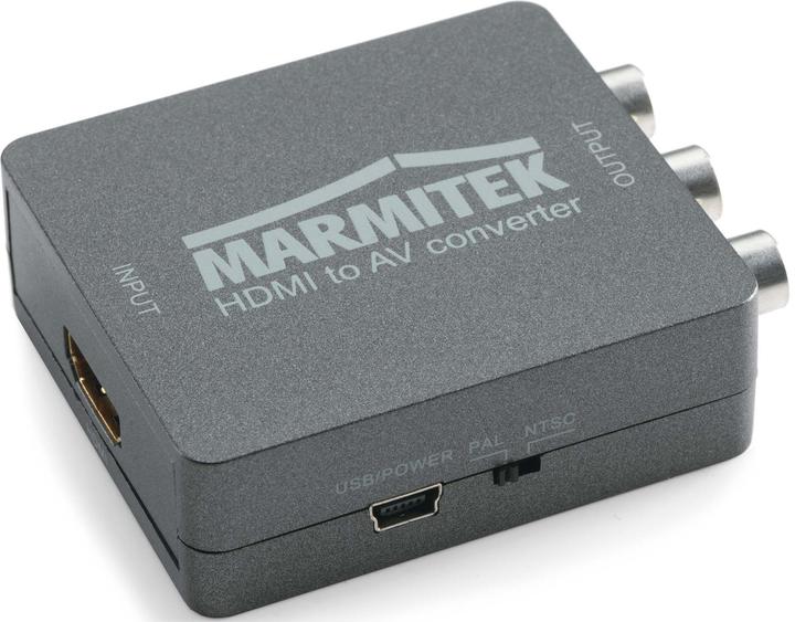
The signal is sent from the entertainment system, e.g. your Blu-ray player, to the splitter. The latter sends the video signal to both the TV – «Out 1» – and the RasPi – «Out 2». There’s a problem: The RasPi doesn’t have an HDMI input. The only HDMI port the mini computer has is an HDMI output. In other words, it can send signals via the HDMI cable but can’t receive signals. The HDMI video signal needs to be converted.
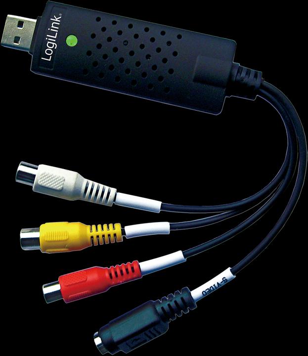
To do this, we use the «HDMI to RCA» converter. This converts the HDMI signal to an AV signal – which stands for audio and video. We set the switch on the HDMI to AV converter to «PAL». Then we hook up the «audio to video» grabber. This converts the AV signal to a USB signal. Lastly, we plug the USB plug into the USB port of the Raspberry Pi. Voilà: the external system is connected to the RasPi.
«But Quentin», it suddenly dawns on me, «what about those HDMI to USB adapters? Why don’t we just use one of those?»
«Because Hyperion is simple software. The DIY kind of brand», the do-it-yourselfer replies, «the grabber needs to send the right signal and that can’t be done with an HDMI to USB adapter».
His explanation is good enough for me. Oh and by the way, we’ve finished.
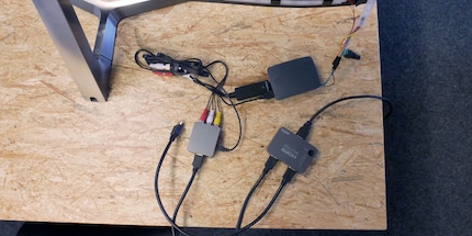
We put it to the test and use the laptop we used for configuring Hyperion as an external entertainment system.
It probably goes without saying that it didn’t work straightaway.
And why should it? It’s not like things were made easy for us. We re-check all components. As already mentioned, we first found out that the switcher is incapable of splitting. That’s annoying. And then Quentin discovers another mistake: The AV grabber we first used is not Linux-compatible. But our RasPi runs Linux.
«That was my fault», Quentin apologises.
«I wouldn’t say so», I reply, «after all, I ordered the goods without double checking.»
Quentin and I lick our wounds, order the new items and postpone the final test to the next day.
Day 4: Here we go!
«Are you ready?», Quentin asks.
«Damn right I am!», I reply.
We start putting up our TV with its DIY Ambilight in a conference room so we can get it as close as possible to a wall. This will help us see the LED effect. One last time, Quentin checks our new hardware: The splitter is splitting and the grabber is grabbing. Excellent. May the test begin.
We are happy.
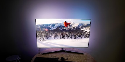
Over the moon.
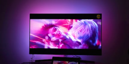
And now for the ultimate test. Is our self-made Ambilight in the same league as the Philips original?
I ask Patrick Eugster, Deputy Store Manager in Zurich. There’s an Ambilight TV on display in the store.
Hi there. It’s me again about our Ambilight project. It worked :D!! Now we’d like to compare it to the real thing. Any chance we can borrow the Philips from our showroom for a few hours? :)
Sure we can. Patrick is cool.
Ciao Luca. The showroom doesn’t look great without the TV :P. But I’ll have it ready for you to collect tomorrow as long as you return it the same day. Thanks ;)
Patrick, in case you’re reading this: Here’s another big thank you to you and your team for helping us transport it. You shop people are awesome!
Day 5: Showdown at the studio
For a week now, Quentin and I have been tinkering, soldering, complaining, cursing, cheering and celebrating. We stuck LEDs to a TV, hooked up a mini computer named after a plant belonging to a subspecies of the rose family and created an Ambilight. Just another week at the digitec office.
I promised to tread this DIY path with you. To the bitter end. And here we are, all ready for that one final test. If you’ve come this far without giving up, you have more than deserved to see the final result. So without further ado, here’s the result.
The big test. DIY vs. original. May the best win!
Conclusion – was it worth all the effort?
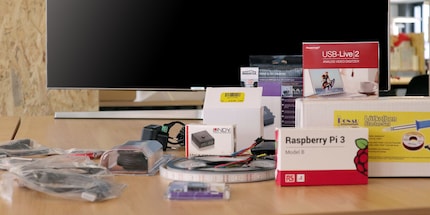
You may be asking yourself if our DIY project is really for beginners. I asked myself the same thing at the beginning and can now say: Yes, it’s ambitious but it’s doable. Sure, I had Quentin, but now you have this manual. Soldering is not a big deal and neither is the Hyperion configuration. However, I can’t promise that you’ll never mess up. Like if the LEDs are flickering instead of glowing. That can happen if the power current isn’t flowing evenly. And it usually means that you did a sloppy job of the soldering.
Sure, there will be moments when you throw up your hands in despair and ask yourself «but why?». But that’s what all DIY projects have in common, right? If it’s any consolation, you’re not alone. The Internet is jam-packed with crazy, extremely helpful people.
Let’s take stock of the effort. We were working on our project for about two hours a day and day five mainly consisted of the video shoot at the studio, so I’m not counting that. So four times two hours make eight hours of work. In other words, you need to invest a full weekend if you want to build an Ambilight. No more.
As regards finances: Quentin and I spent about 380 francs. Frankly, that’s more than I had expected. The expensive bits are the LED tape, the Raspberry Pi starter set, the splitter and the grabber. Then there are all the other bits and bobs. They don’t cost much, but it all adds up.
What about the actual Ambilight?
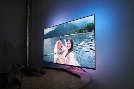
The Philips Ambilight shines brighter and further than our DIY Ambilight. That is because the Philips LEDs are mounted at an angle and don’t illuminate the wall directly. By contrast, our Ambilight has more LEDs, making the projected light more matched to the image on the screen. The video shows this quite well from 1:28. The DIY Ambilight shines precisely where it should. The dark areas remain dark and are not outshined by LEDs that are close. I actually think it’s a good thing that our Ambilight doesn’t illuminate the entire wall – it’s less distracting and you focus more on the actual content.
Whether it’s worth the effort depends on how much time and money you are willing to invest. Personally, I’m not a big fan of the Ambilight. Maybe that’s why I prefer our more subtle and precise DIY Ambilight.
I hope you enjoyed our video and now I hope you enjoy having a go at this project yourself!
I write about technology as if it were cinema, and about films as if they were real life. Between bits and blockbusters, I’m after stories that move people, not just generate clicks. And yes – sometimes I listen to film scores louder than I probably should.
From the latest iPhone to the return of 80s fashion. The editorial team will help you make sense of it all.
Show all