
Background information
3D printing - four helpful answers for beginners
by Marc Schaffer

You can buy adapters, if they are available. Or you can design and 3D print one yourself. In this case, I want to mount an HTC Vive Base Station on a microphone stand. Unfortunately, both have different sized threads (English/Imperial), so I need an adapter.
In this tutorial, I will show you how to quickly and easily programme an object with OpenSCAD. OpenSCAD is a programme with which you can create 3D models. The software is free and works on Linux, Windows and Mac. Instead of the usual CAD programmes, however, you don't draw an object here, but type it in with your keyboard in the form of code. But don't worry, it's not incredibly complicated and you don't need any more maths knowledge than with other drawing programmes. To help you remember, you can find a CheatSheet here.
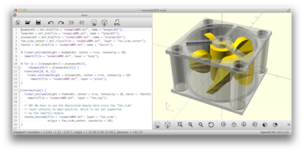
The work process is divided into four steps:
Before you can start drawing, or in this case programming, you need to gather the materials you have available. Using various tools such as a ruler, set square or callipers, measure everything out precisely. The more precise you are in this step, the fewer problems you will have when assembling the objects at the end.
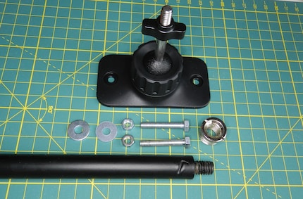
The holder, which I measured in the previous step, has the following dimensions: Length = 84.2 mm; width = 44 mm. The screw has a diameter of 3 mm and a length of 18 mm. To obtain the basic cube, we type the following into the text field: cube([84.2,44,18],centre=true);
After that, we just press "F5" and the cube is visible as a 3D model.
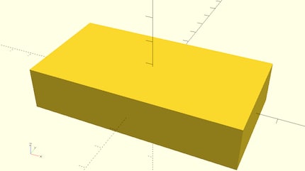
The object was centred with the instruction "center=true". The zero point is therefore exactly in the centre. This is very practical in our case, as the object is symmetrical, i.e. both sides are the same size. As a result, the holes for the thread and the screw are in the centre and we have to calculate less for the following M5 holes.
We could now add the holes, but it doesn't fit so nicely with the Lighthouse when it's so angular.
As only the outer edges are rounded, we use the "hull" function, which draws a hull around the objects. Now it gets a bit mathematical: The rounding has a radius of 10 mm, so we place 4 cylinders at the corners and stretch the hull around them:
hull(){
translate([(84.2/2)-10,(44/2)-10,0]) cylinder(r=10, h=18,centre=true);
translate([(-84.2/2)+10,(44/2)-10,0]) cylinder(r=10, h=18,centre=true);
translate([(84.2/2)-10,(-44/2)+10,0]) cylinder(r=10, h=18,centre=true);
translate([(-84.2/2)+10,(-44/2)+10,0]) cylinder(r=10, h=18,centre=true);
};
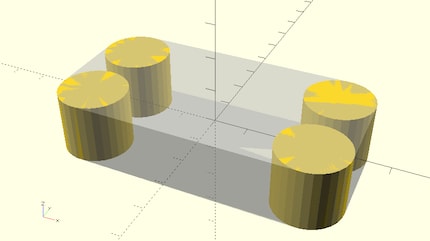
Starting from the zero point in the middle (centre), I move half the length and half the width of a cylinder away from the zero point ("translate" determines the new position) and subtract the radius. I only have to write this down once and can then reuse it for the other cylinders - sometimes plus from the zero point and sometimes minus from the zero point. (Oh, if only maths had been explained to us in such a clear and easy-to-understand way at school. You just have to apply it to understand it)
You can make objects transparent by writing a "%" in front of them, without which a full object should now be visible.
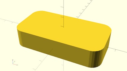
Now let's add the holes by adding various cylinders. These are then calculated away from the large object ("drilled"):
SILF=0.6;
translate([0,0,0]) cylinder(r=5+SILF, h=50,centre=true);
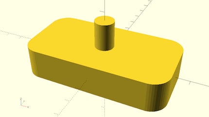
It is important that the (minus) objects to be billed are larger and protrude, otherwise the edges will not be nice and the 3D printer will try to close the hole with a thin layer.
The 3D printer, or rather some slicers that calculate the objects for the 3D printer, have the annoying peculiarity of printing the holes smaller than specified. The hole must therefore be planned larger by this shortfall. I have called this "Slicer inner hole error" and add this variable "SILF" to the hole. You can freely name the variable, but you should not programme the correction amount as a fixed value. Every printer is different and programmes change. When making changes, you only need to change the variable at the beginning and not all the holes.
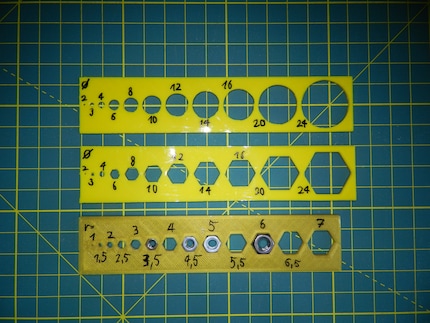
This only requires 1 line for the objects:
for (i = [0:.5:7]) { translate([(ii2)+i*2,0,0]) cylinder(r=i, h=5+i,centre=true); }
"for" loops are a practical tool when programming, but let's get back to the adapter. Let's "drill" the hole by forming the difference of A minus B. Large hull object minus screw cylinder with the function "difference":
difference(){
hull(){
translate([(84.2/2)-10,(44/2)-10,0]) cylinder(r=10, h=18,centre=true);
translate([(-84.2/2)+10,(44/2)-10,0]) cylinder(r=10, h=18,centre=true);
translate([(84.2/2)-10,(-44/2)+10,0]) cylinder(r=10, h=18,centre=true);
translate([(-84.2/2)+10,(-44/2)+10,0]) cylinder(r=10, h=18,centre=true);
};
translate([0,0,0]) cylinder(r=5+SILF, h=50,centre=true);
}
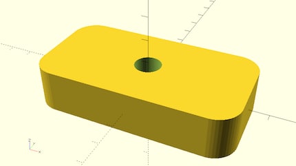
Now let's add the two holes for the M5 screws. To do this, we expand the "B" part, which only consists of the cylinder for the thread, into a group:
group(){
translate([0,0,0]) cylinder(r=5+SILF, h=50,centre=true); //Thread from the tripod
translate([32,0,0]) cylinder(r=2.5+SILF, h=50,centre=true); //M5 screw
translate([-32,0,0]) cylinder(r=2.5+SILF, h=50,centre=true); //M5 screw
}//group
An important tip: The text after the "//" are comments and are ignored by the programme. If you want to adjust something two months later, it saves a lot of time, as you can read in the comments what and why, for example, there had to be 1 mm more!
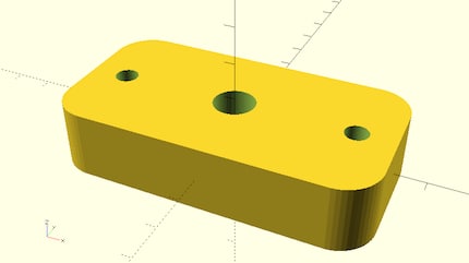
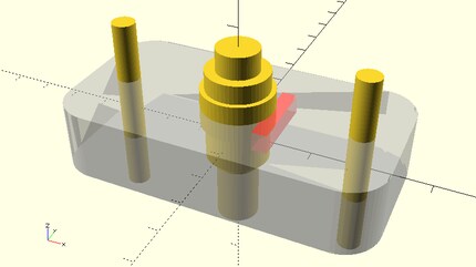
Now all that's missing is the hole for the large screw. To do this, we add the two cylinders (for the screw and one for the edge). However, these should not be continuous, but should rest on 3 mm of material. The Z-axis must therefore be adapted:
translate([0,0,-(18/2)+3]) cylinder(r=(15.5/2)+SILF, h=25,centre=false); //Adapter
translate([0,0,-(18/2)+3+10]) cylinder(r=(18/2)+SILF, h=10,centre=false); //Adapter border
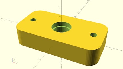
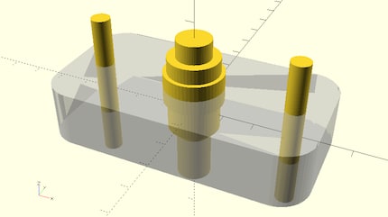
We are almost finished. The object could be printed like this, but the screw would have to be laboriously tightened and everything would have to be dismantled to unscrew it, as the screw has no stop and would turn loosely. So we add a stop point and saw off part of the edge of the screw to create a "D-cut".
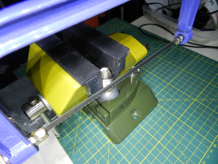
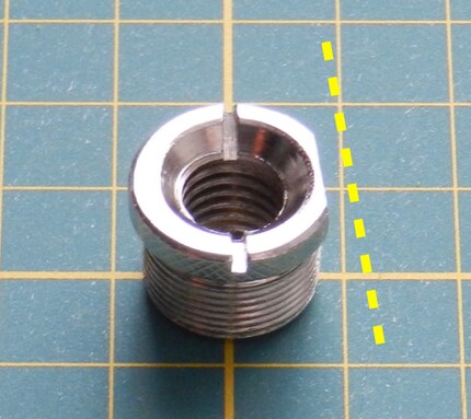
At the end, let's add the stop point on the object - a one-liner at the end:
translate([(15.5/2)+0.3,-10,(18/2)-5]) cube([4,20,5],centre=false); //D-Cut support
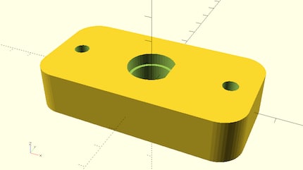
To make the edges even smoother, we increase the number of edges per circle: $fn=150;
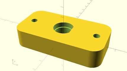
This should only be done at the end, however, as it increases the computing time. Incidentally, you can also use this to generate 6-corners, for example: cylinder(d=20,h=10,$fn=6);
Now the programme only needs to calculate the 3D model in high resolution. This is called rendering and can be exported as an STL by pressing "F6". The STL file can then be converted by the slicer for the 3D printer and printing can begin! You can read exactly how this works here:
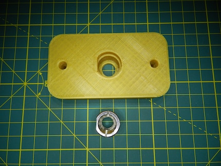
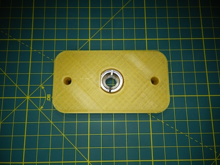
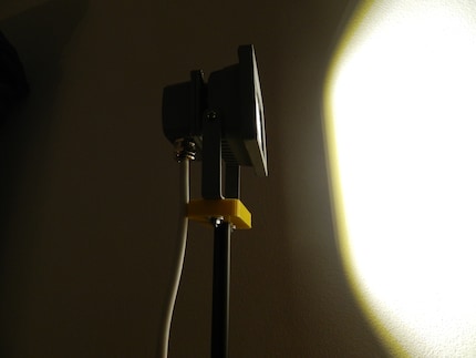
If you have worked modularly, you can continue to use the file and adapt it for other applications. For example, as a holder for a construction lamp.
If you would like to build this adapter yourself, you can copy the entire source code and paste it into your OpenSCAD.
$fn=150; // Number of edges of a circle
SILF=0.6; // Slicer inner hole error, if the slicer prints the inner holes too small
//%cube([84.2,44,18],centre=true);
//#cube([68.4-5,44,18],centre=true); //difference test
difference(){
hull(){
translate([(84.2/2)-10,(44/2)-10,0]) cylinder(r=10, h=18,centre=true);
translate([(-84.2/2)+10,(44/2)-10,0]) cylinder(r=10, h=18,centre=true);
translate([(84.2/2)-10,(-44/2)+10,0]) cylinder(r=10, h=18,centre=true);
translate([(-84.2/2)+10,(-44/2)+10,0]) cylinder(r=10, h=18,centre=true);
};
group(){
translate([0,0,0]) cylinder(r=5+SILF, h=50,centre=true); //Thread from tripod
translate([0,0,-(18/2)+3]) cylinder(r=(15.5/2)+SILF, h=25,centre=false); //Adapter
translate([0,0,-(18/2)+3+10]) cylinder(r=(18/2)+SILF, h=10,centre=false); //Adapter border
translate([32,0,0]) cylinder(r=2.5+SILF, h=50,centre=true); //M5 screw
translate([-32,0,0]) cylinder(r=2.5+SILF, h=50,centre=true); //M5 screw
}//group
}//diff
translate([(15.5/2)+0.3,-10,(18/2)-5]) cube([4,20,5],centre=false); //D-Cut edition
Good luck!
I am a digital aboriginal of the generation Commodore 64, online since dial and acoustic coupler. Besides video games, I like to bring things from cyberspace into makerspace with the 3D printer. Technology is simply fascinating.
From the latest iPhone to the return of 80s fashion. The editorial team will help you make sense of it all.
Show all